PARTICLES AND PROCEDURAL FX - SCAD S25
April 13, 2025 - Technical Pyro Setup and Test Cache/Render
For my project going forward, I plan on using Redshift instead of Karma. As much as I enjoy Karma, I find it to be slower when it comes to navigating not just the viewport render but materials and lighting changes. My machine runs smoother when using Redshift rather than Karma when I am not currently rendering to disk, so for ease of the process, I will be using Redshift.
To start this week, I took my POPnet, cached it out and transformed it slightly above the ground plane. I added a timewarp to set my cache frame range to 300 frames. I then clipped anything 10 units above the origin to exclude any particles getting lost under the plane. This motion becomes my “Track” of the tornado, which is the motion I will use later down the line in the simulation. I cleaned up the attributes and set value of pscale to fit within 0-0.645. Here is that setup in the node tree!


Next, I took a for-each node, retiming it to not interpolate the position so that my velocity isn’t “rebaked.” In the for-each, I am adding more retimed iterations of my particle POP. This creates a thicker particle sim that I can adjust further.


I then took an add node to trace the id attribute for the particle path, then resample them to get a “jittered” variation.
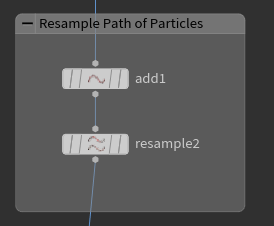

I then took a pyro source to get a density attribute in the particle path. This is another thing I am using from our last project we did in V428.


Next, I set up a volume rasterize from attribute node tree. Within the node, I am using both the density attribute and velocity attribute to build a voxel volume. I added some slight velocity blur and had larger voxel sizes to rid the banding. I am using the density attribute to adjust my coverage scale. This was a good to “paint” my points into voxels while controlling the resolution of the volume.

I then take this voxel volume and feed it into my DOPnet for my pyro simulation.
The next part of this process was building up my pyro solver and using what I have made previously as a “mask” for this simulation. Here are some of the adjustments I made.
I create my simulation with a division size of 0.5 to have a fair bit of detail in my smoke.
Using a Gas Resize Fluid Dynamic node, I resized the bounding of my dynamic simulation. I took my “Track_OUT” from the POPnet to add the motion and shape for my tornado. However I adjust my POPnet simulation, it will directly impact the shape of my simulation. I adjust the padding/threshold for this object so that it isn’t forced in the bound of the POP simulation.
I used the Gas Turbulence node to add some randomness and noise to my Pyro’s velocity. I also wanted to add some drag force to my simulation but was getting odd results with the Drag node so I settled for adjusting the velocity in a wrangle node.
For the post-solve part of my solver, I use a Volume Source node to set the density and velocity based on previously made attributes.
I also adjusted the buoyancy lift so that full control of the sim shape is in the control of the track. I also changed the dissipation so that the time/age of the smoke is controlled.
Here is the node setup within my DOP and the result cache simulation.


For the last thing I did this week, I wanted to add some spin to my turbines.
Before my for-each node, I took a wrangle node and used this code to create an attribute offset.
I@offset = int(fit01(rand(@ptnum + 1), -25, 50));
Within the for-each node, I attach a spare input from the Offset into the timeshift to allow a shift parameter in the node. Here is that node setup.

Here is a quick test render with my current camera in Redshift.
I will not be having my tornado start from the ground up, I just have yet to adjust this timing.
April 6, 2025 - Preliminary Particle POP and Further Research
For this week, my main focus was finding both references and resources that would help me chip away at this project, going from the big picture to eventually the fine details. Using some advice from Professor Fowler (https://deborahfowler.com/), I went searching for not only more references but guides for building this twister.
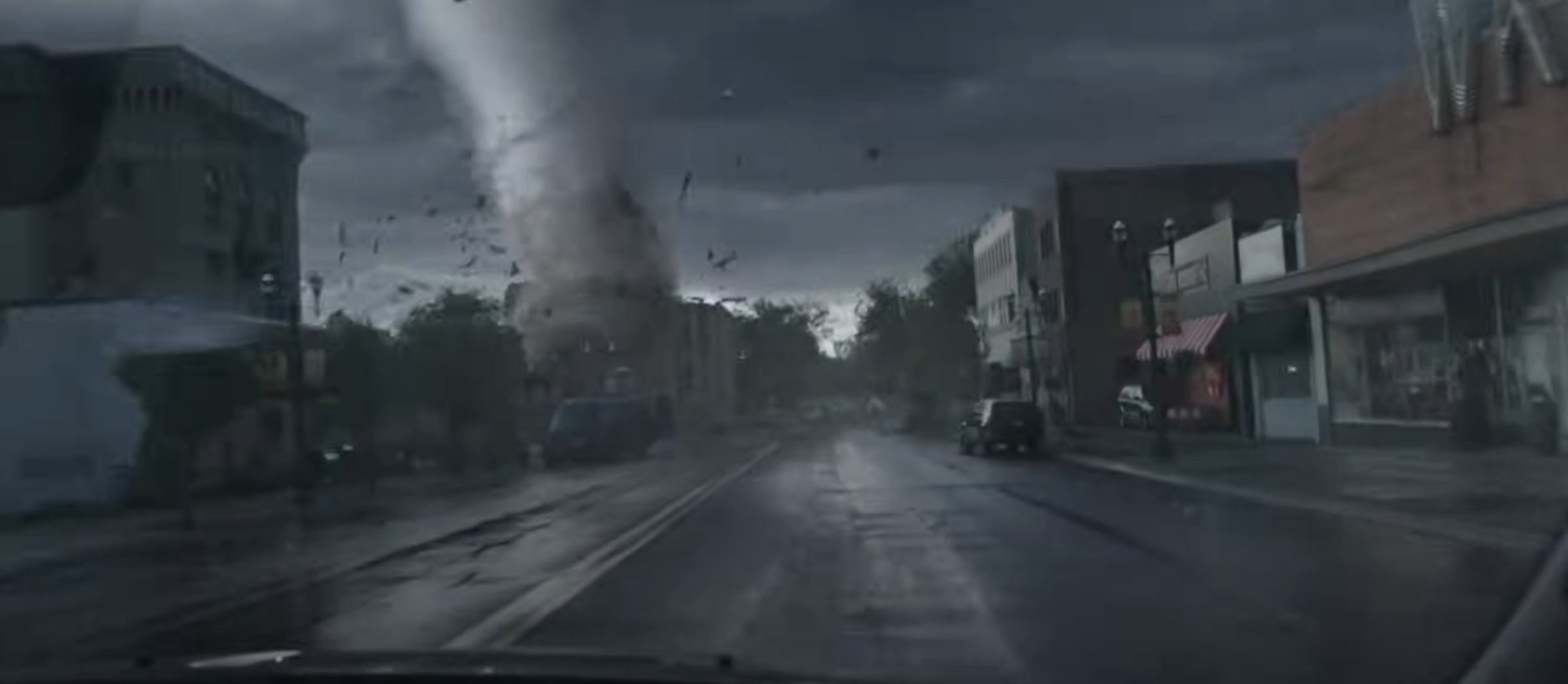
First I began looking at more detailed references for my tornado. Since iPhone cameras typically have a difficult time capturing clear images in huge twister storms, I looked at some movie and CG references to help me see the actual level of detail some twisters have
Here are some reference images and links I have found for this.
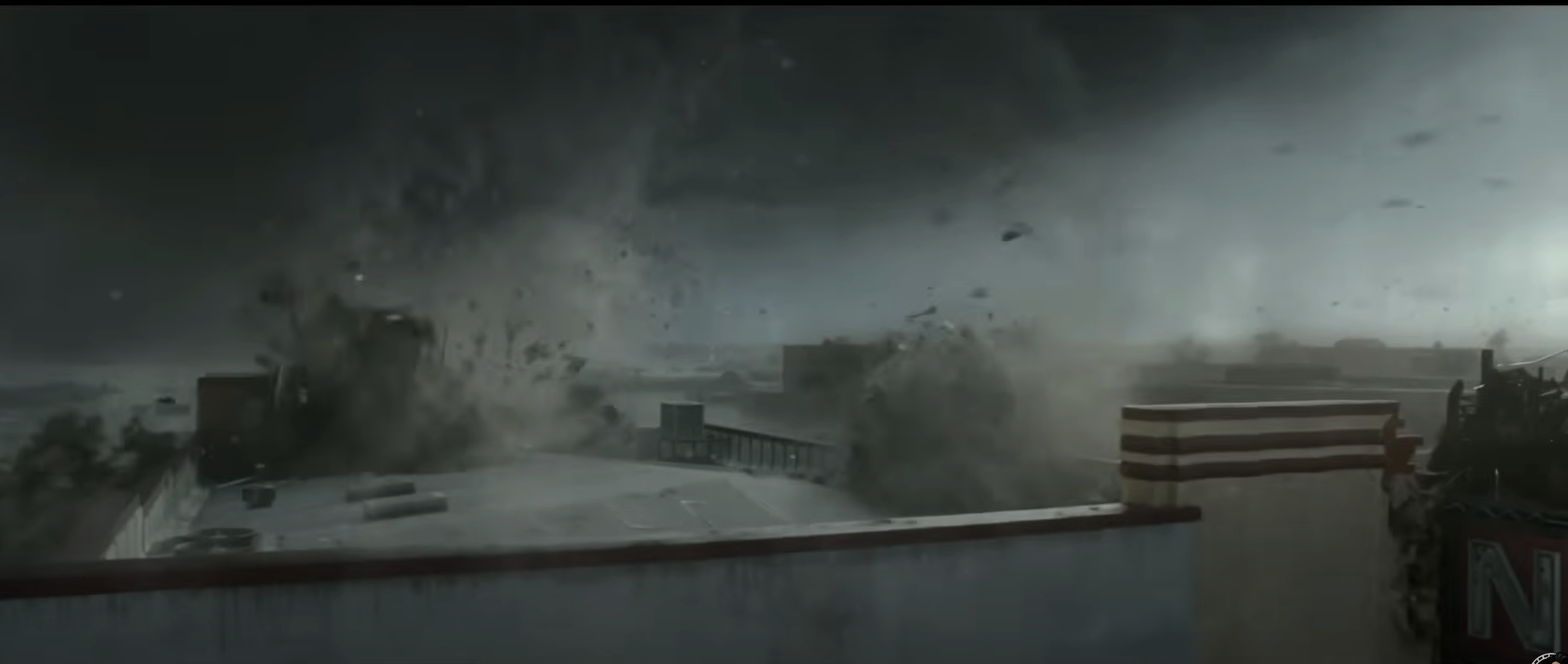
Twisters (2024) - There isn’t great detail in tornado itself, but I found the destruction/debris at 7:30 particularly interesting.
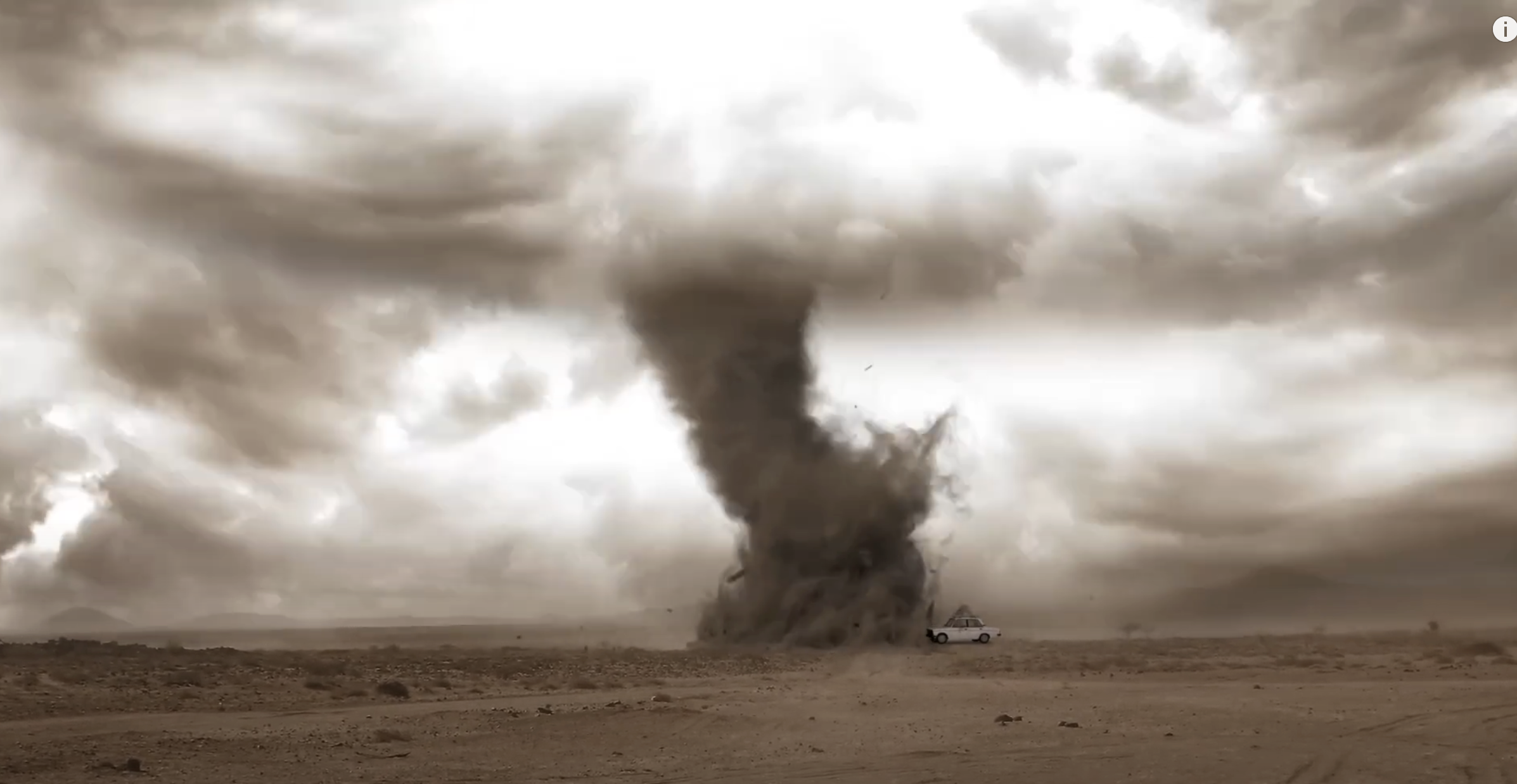
From Professor Fowler, she directed me to some professional breakdowns on movies like Superman (2013) from companies like Scanline VFX. Here is that reference.

Here are some other references from youtube of varying tornados, though some have different levels of rendering and quality, any references is helpful for this project.
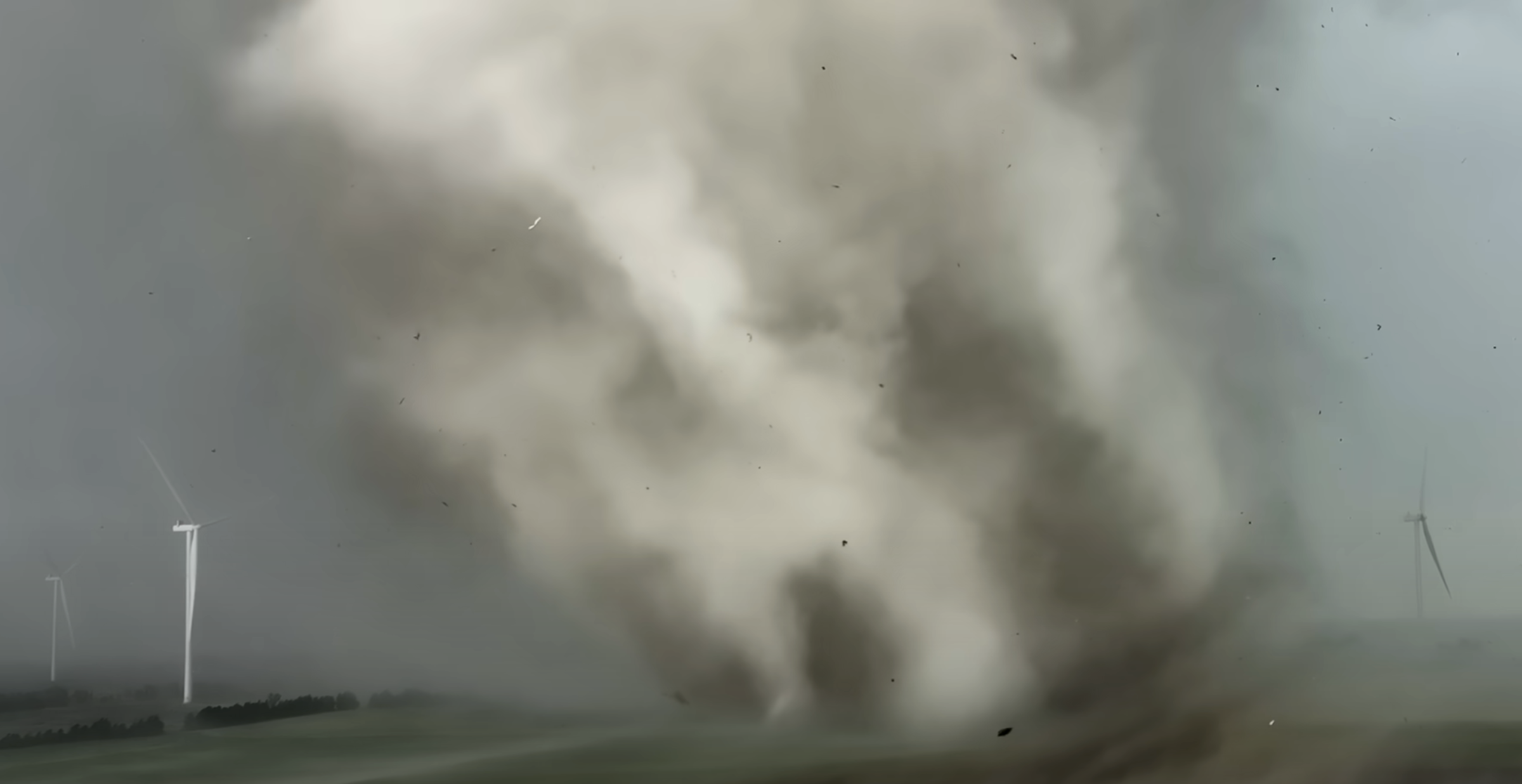
This is a documentary/news package I found that dives into the history and journalistic science of how super tornados are formed.
This week, I dove into creating my tornado in Houdini. I know the “why” and the “what,” but the “how” was my biggest challenge for this project. Professor Fowler directed me to the OdForce forum (https://forums.odforce.net/), where many artists within Houdini troubleshoot and solve problems for each other. I spent a lot of time on this forum addressing many of the issues I encountered.
I began by breaking down the different levels of the tornado. From my research, it seems there are four main parts of a tornado: the debris cloud (bottom), the funnel cloud, the spiral updraft, and the condensation funnel (top). To create the body of the funnel, I decided to use a line as my “path,” and employed two POP kicks to generate points. Essentially, I created points on two separate scatters and had them twist around my path.
Initially, I thought I could get away with using a POPCurve in DOPs, but that didn’t give me enough control or the physicality I wanted for my vortex. So, I decided to use either VOPs or VEX within DOPs. Before diving into that, however, I first built my elements. Here is the graph of nodes, with my three inputs.

For my ground plane, I used the adjusted plane from my turbine SOP and extruded it upwards. I then applied an isooffset to create a shell or volume from the geometry, onto which I scattered points (alternatively, I could have used the "Points from Volume" node for this). Below is how it looks in the viewport.


I did something similar for a ring shape (circular base of the twister), but animated a mountain node to add some variation and movement in the scatter.


Next, I set up a POPnet at the SOP level to help visualize my scene more effectively.
For this setup, I was able to quickly build the VOP network. Here's a breakdown of what each part of the network is doing.
I start by creating a point cloud based on the line I made earlier, searching within a radius of 65 units (my scene is quite large compared to the “TommyGEO” size).
In the point cloud, I filter out the attributes “P,” “tangent,” and “curveu” into their respective spots.
“P” is used to filter the points
“tangent” filters the direction of the line
“curveu” filters the curve path on the line
The filtered “P” attribute from input01 is then subtracted from the global “P” attribute.
After that, I take the subtraction and cross-produce it with the tangent (resulting in a perpendicular vector). I then normalize the vector and multiply it by a constant (currently set to 1, but this can be changed to affect the shape).
I also take the inverse of the constant multiplication of the tangent to control the height—lower values result in a higher vortex in relation to the line’s tangent.
For the shape of the vortex, I feed the “curveu” into a ramp. Based on the float value from the ramp, and within the fit range, this defines the shape of the twister.
To add some random thickness to the twister, I randomize the “id” attribute of my global points, setting it to the range of the float values.
I then multiply everything that affects the thickness/width and add it to the height, along with the previously subtracted points.
Finally, I bind out the random displacement of points to be used in higher parameters within the VOP.
Below is the VOP node tree and the result in the POPnet.

It took some head scratching and a little bit of time, but I wanted to build this network using VEX as well, mainly to expose myself to both sides of the coin and see if I could understand both. I will say I had more fun problem-solving the VEX code for this, but VOPs were significantly easier to follow when it came to understanding where attributes/filters were going.
The setup and process are identical to what was described above. Here is the VEX snippet in the POP Wrangle node.


I then added some forces like drag and counter forces to add some realistic jitter and movement. These values will likely evolve over time.

Here is a side by side playblast of both the VEX code and VOPs working in my POPnet.


VEX VOP
Input variables are slightly different; VEX is closer to the desired path, thickness, and twister motion.
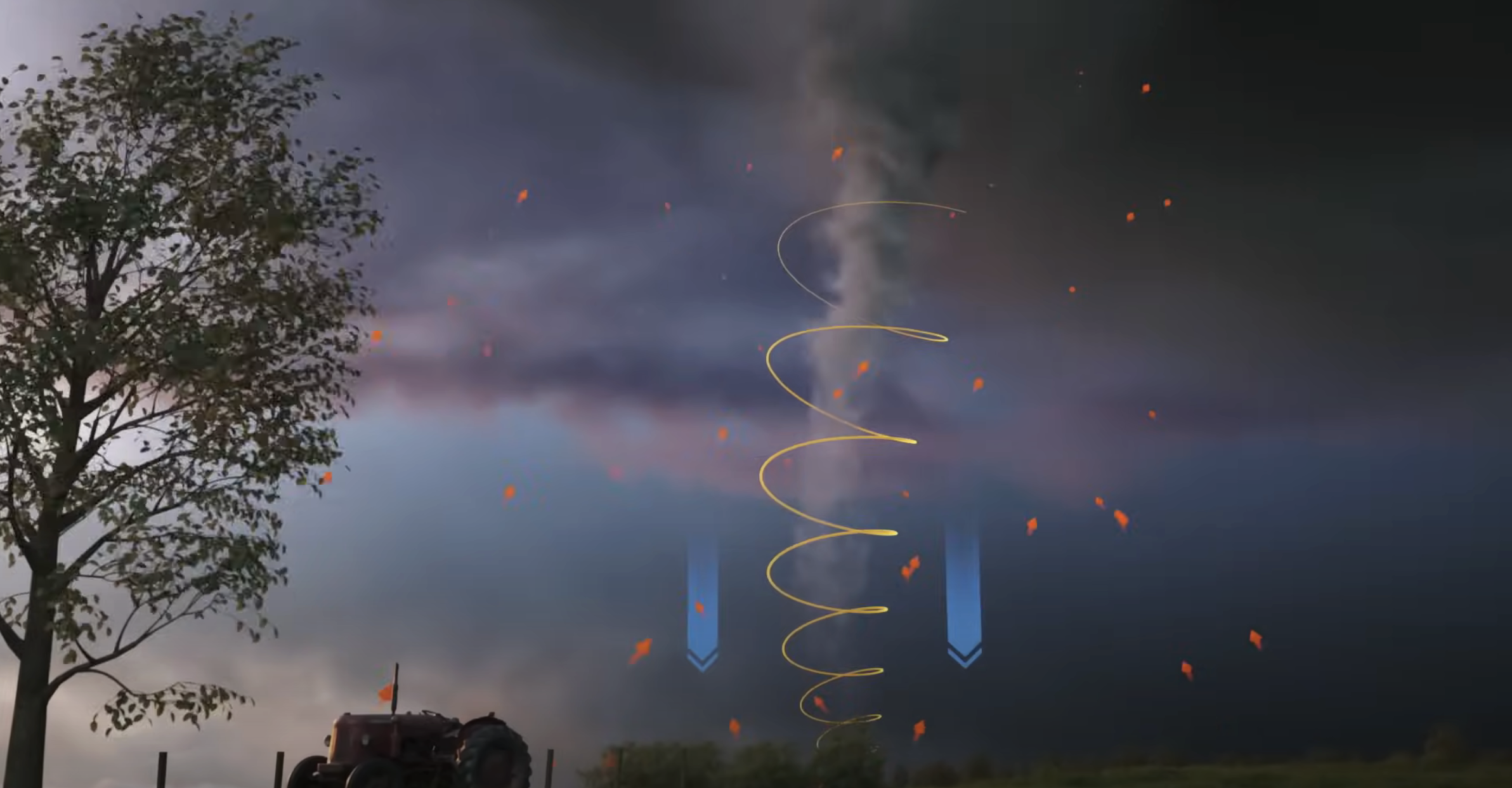
This playblast shows the relative scale of the tornado I am looking to achieve. It is not yet the correct shape or velocity, but now that the VEX and/or VOP code is set up, depending on which one I use, I can adjust the values for velocity, thickness, shape, and size of the twister. Two of these are top-level constraints that can be handled in the wrangle, but the other two can easily be converted into artist-friendly controls.
In my later version, I will retime the particles so that they start from the ground at the beginning of the scene.
March 28, 2025 - References and Layout
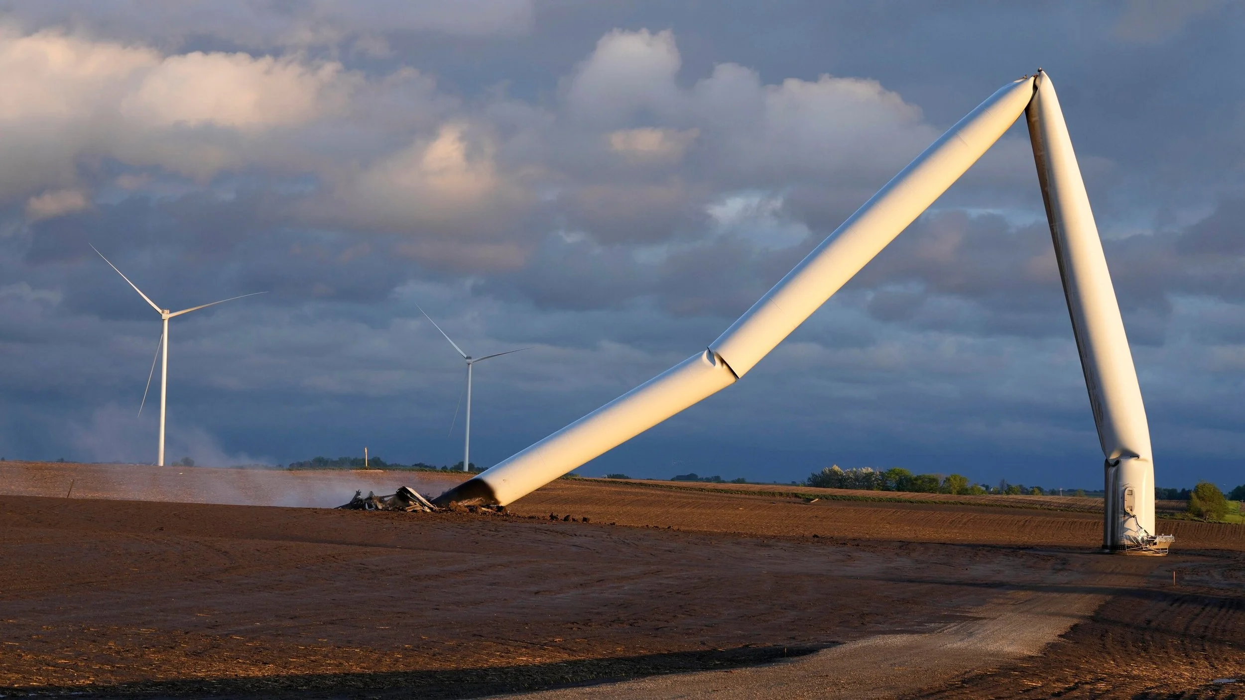
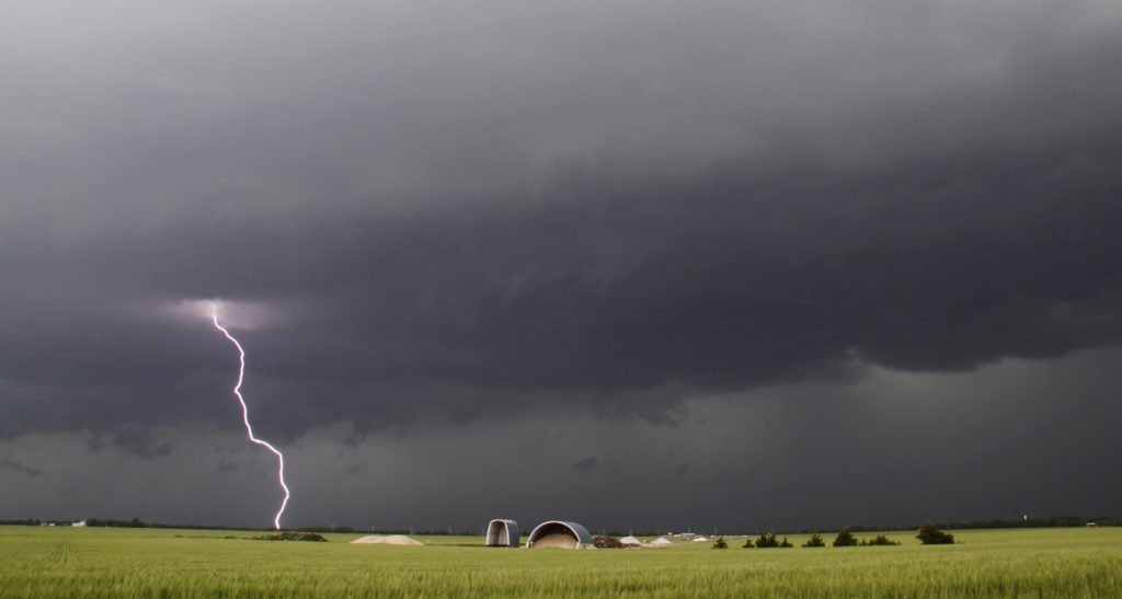
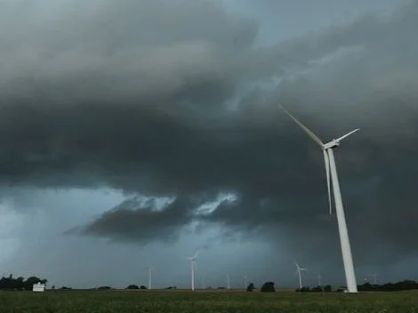
This Blog is mainly going to be focused on the final project for the quarter in VSFX428 - Particles and Procedural FX. For my project I am planning on doing a tornado FX simulation. This project is FX based, so my main focus will be on that, but as I am a lighting/compositing artist, I am excited to take this project beyond the FX. I have been doing much research on this and want to do a scene in an open Wind Turbine field. Not a huge lot of destruction, but I plan on doing a hero one with a foreground turbine.
Here are some references I have been collecting for this project.


Here is some gif animations for some video references


I also took some of these references and some prompt into DeepAI to build a scene layout for what I was thinking as far as shot design and mood. Here is the best option I got, some were VERY unrealistic.

For this project, I want to render out layers of my simulation for compositing and render time purposes. Here are the layers I am expecting to need.
Core Surface Simulation - Tornado 03
Core Surface Detail Simulation - Tornado 02
Ground Simulation - Tornado 03
Large Scale Ground Simulation - Impact
Foreground Debris Simulation
Debris Simulation - Wind Turbine
Controlled RBD Simulation - Wind Turbine
Lightning Simulation - If Time Permits
Fence Beauty
Turbine Beauty
Greenery Beauty
Sky Comp
These are subject to change, and for the FX, a large part will be rendered together to help with less trips to the farm.
I am fully seeing this project as something I come back to from time to time and evolve over time.
I began some technical preliminary layout this week to get this project rolling.
I knew I wanted to build this scene procedurally, so beginning with the ground plane, I moved the points along the Normal using VEX, and subdividing for a smooth surface. I took the unsubdivided layout and randomly roomed some points to add variation, I used P.y for this since those are the points with the most variation. I also added some boundaries for P.x and P.z since I wont need turbines all over/behind the camera (Scene will be culled to the frustrum eventually). Here is that process of laying out the turbines.


Here is the current node tree for this setup, I have broken apart the wind turbine asset for better control and imports.

For the fences, they were built using cubes and simple mountain @N noise since they aren’t huge in the scene. For laying them out I am taking a for each node, using the bounding box and iteration # of the fences to build the row procedurally. I am also using the minpos() of the points on the grid so that wherever I lay the fences, they will conform to the flow of the ground. Here is that node setup as well as the viewport view.


One of the final preliminary things I wanted to begin was the camera movement. If I can lock the camera early, this will help me later down the line for lighting/rendering. I started with a simple camera animation, then added some MotionFX noise to both the rotation and the focal zoom. Here is that view in the animation and noise editor.


Here is the viewport playblast of the current movement I am working on! Where the camera zooms, the turbine will be bent and destroyed by the wind force of the tornado.
I have also started some initial lookdev on the turbine and fences. These details aren’t super visible, so the quality of the maps wont be super high or strong. I build these in adobe Substance Painter.
I plan on rendering in Karma CPU in this project as I want to do more work within it overall!
Turbine References:


Fence References:


